
Lighting Calculations — Lumen Method, Point-by-Point & Software Tools
From quick manual estimates to precision simulation — every method a designer needs.
Why Lighting Calculations Matter
Lighting calculations are the bridge between design intent and real-world performance. They ensure you achieve the required illuminance levels (lux), uniformity, and energy compliance before a single fixture is installed. In the GCC market, proper calculations are mandatory for municipality approvals, ESTIDAMA/LEED compliance, and client sign-off. Three methods form the hierarchy of lighting calculation: 1. Lumen Method — Quick manual calculation for regular rectangular spaces. 2. Point-by-Point Method — Precise calculation at specific locations using photometric data. 3. Software Simulation — Full 3D modeling using DIALux, Relux, or AGi32 for complex geometries and comprehensive analysis.
The Lumen Method (Utilization Factor Method)
The Lumen Method is the fastest way to estimate the number of luminaires needed for a uniform lighting layout. It works best for regular rectangular rooms with uniform ambient lighting. The core formula: N = (E × A) / (F × UF × MF) Where: • N = Number of luminaires required • E = Required illuminance in lux (from EN 12464-1 or project brief) • A = Area of the working plane (m²) • F = Luminous flux per luminaire (lumens) • UF = Utilization Factor (how much light reaches the working plane) • MF = Maintenance Factor (accounts for lumen depreciation, dirt, and aging)
Worked Example — Open Plan Office
Room: 12m x 8m = 96 m² | Required: 500 lux (EN 12464-1) | Luminaire: 4000 lm LED panel | UF: 0.65 (medium reflectances) | MF: 0.80 (LED, 3-year cycle) N = (500 × 96) / (4000 × 0.65 × 0.80) = 48,000 / 2,080 = 23.1 → 24 luminaires Layout: 6 × 4 grid. Spacing: 2.0m × 2.0m. Check: spacing-to-height ratio = 2.0/2.8 = 0.71 (within typical SHR max of 1.5 for these panels).
Understanding Utilization Factor (UF)
The Utilization Factor is the ratio of luminous flux reaching the working plane to the total flux emitted by the luminaires. It depends on: • Room Index (RI): RI = (L × W) / [Hm × (L + W)], where L = length, W = width, Hm = mounting height above working plane. • Surface Reflectances: Ceiling (typically 0.7), walls (0.3–0.5), floor (0.2). • Luminaire Type: Its light distribution (direct, indirect, direct/indirect). Manufacturers provide UF tables in their technical datasheets, listing UF values for different Room Index values and reflectance combinations. A higher Room Index (larger room or lower mounting height) gives a higher UF. For rooms with Room Index < 1.0 (small or tall rooms), UF drops significantly — consider using more, smaller luminaires rather than fewer large ones.
Maintenance Factor (MF)
The Maintenance Factor accounts for the inevitable reduction in light output over time. It's the product of several components: MF = LLMF × LSF × LMF × RMF Where: • LLMF (Lamp Lumen Maintenance Factor): LED lumen depreciation over time (e.g., L80B50 at 50,000h → LLMF = 0.80). • LSF (Lamp Survival Factor): Probability the LED module is still operational (typically 0.99 for quality LEDs). • LMF (Luminaire Maintenance Factor): Dirt accumulation on the luminaire (0.85–0.95 depending on IP rating and environment). • RMF (Room Maintenance Factor): Dirt on room surfaces reducing reflectances (0.90–0.95 for clean environments). For GCC environments with high dust: Consider MF = 0.70–0.75 for open environments, 0.80 for sealed IP65+ fixtures in clean interiors. The CIBSE SLL Code for Lighting (2022) and CIE 97:2005 provide detailed MF calculation guidance.
Typical Maintenance Factor Values
| 0 | 1 | 2 | 3 |
|---|---|---|---|
| Clean office (AC, sealed) | IP20-IP40 | 3 years | 0.80 |
| Retail / hospitality | IP20-IP44 | 2 years | 0.77 |
| Light industrial | IP54-IP65 | 2 years | 0.73 |
| Heavy industrial / dusty | IP65-IP66 | 1 year | 0.65 |
| Outdoor — sheltered | IP65 | 2 years | 0.72 |
| Outdoor — exposed (GCC) | IP66-IP67 | 1 year | 0.65 |
| Parking garage | IP65 | 3 years | 0.70 |
| Clean room | IP65 sealed | 1 year | 0.85 |
Point-by-Point Method
The Point-by-Point method calculates illuminance at a specific point on a surface from a specific luminaire. It's essential for accent lighting, spot calculations, and verifying critical task areas. The Inverse Square Law formula: E = (I × cos θ) / d² Where: • E = Illuminance at the point (lux) • I = Luminous intensity toward the point (candela, from IES file) • θ = Angle of incidence (angle between the light ray and the surface normal) • d = Distance from the luminaire to the point (meters) For multiple luminaires, calculate the contribution from each and sum them. This is the fundamental calculation that software tools automate across thousands of grid points.
Worked Example — Accent Spotlight
A spotlight with 5000 cd peak intensity is mounted 3m above a display at 30° from vertical. d = 3m / cos(30°) = 3.46m E = (5000 × cos 30°) / 3.46² = (5000 × 0.866) / 11.97 = 362 lux This is the illuminance on the horizontal plane from this single fixture. For vertical illuminance on the displayed object, the calculation uses sin θ instead of cos θ.
Software-Based Calculation — DIALux & Relux
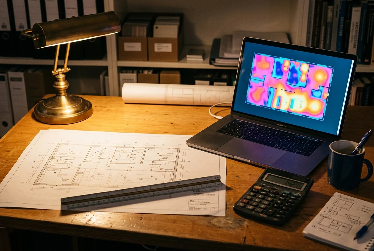
For real projects, software tools perform thousands of point-by-point calculations across a 3D model. The two industry-standard tools are: DIALux (Free): The most widely used lighting design software globally. Features include 3D room modeling, IES/LDT file import, automatic luminaire placement, compliance checking (EN 12464, emergency lighting), energy calculations (LENI), and high-quality rendering. Relux (Free): Strong alternative with excellent BIM integration. Features include Revit/IFC import, RSMX files for parametric luminaires, daylight simulation, and automatic compliance reports. AGi32 (Commercial): Professional tool favored in North America for complex outdoor, sports, and roadway calculations. Advanced features for large-scale site lighting. Key outputs from software simulation: • Average illuminance (Eavg) on the task plane • Minimum illuminance (Emin) and uniformity ratio (U0 = Emin/Eavg) • UGR (Unified Glare Rating) at defined observer positions • Vertical illuminance and cylindrical illuminance • False-color plots showing lux distribution • Energy metrics: Lighting Energy Numeric Indicator (LENI) in kWh/m²/year
Spacing-to-Height Ratio (SHR)
The Spacing-to-Height Ratio determines the maximum distance between luminaires to maintain acceptable uniformity. SHR = S / Hm Where S = spacing between luminaires, Hm = mounting height above working plane. Every luminaire has a maximum SHR (SHRmax) determined by its light distribution — published by manufacturers. Exceeding SHRmax creates dark spots between fixtures. For recessed downlights: SHRmax typically 1.0–1.5 For LED panels (600x600): SHRmax typically 1.3–1.7 For linear continuous: SHRmax can be effectively unlimited along the run Always verify spacing with software simulation — SHR is a guideline, not a guarantee of uniformity.